Emotive Robot
The emotive robot is a machine designed to display 3 different emotions based on distance calculated by the ultrasonic sensor, along with that it is also able to look around thanks to the pan and tilt servo brackets if programmed to do so. It can also display any message on its LCD display and since the byte maps for the emotions are global they can be changed with ease.
| Engineer | School | Area of Interest | Grade |
|---|---|---|---|
| Eeshan | Lynbrook High School | Unknown | Incoming Junior |

Final Milestone
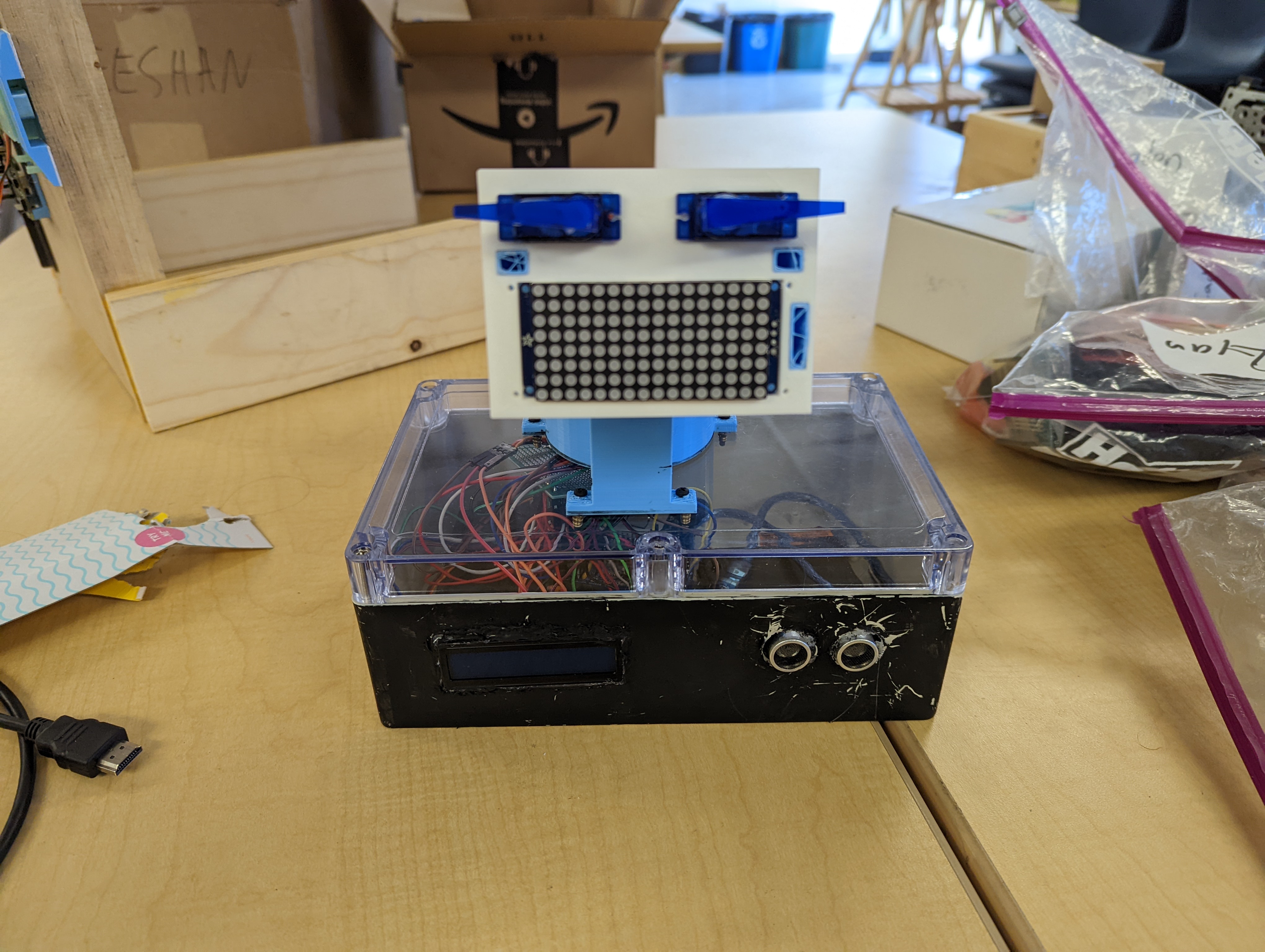
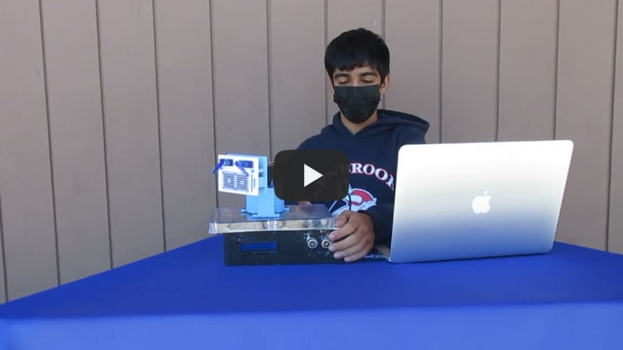
For my final milestone I made mostly cosmetic changes. I made the pan and tilt more fluid and quick so it also can double as an idle motion. I also painted the front of the robot black so it looks cleaner and nicer to look at. I had to use eletrical tape on the edges, LCD display, and ultrasonic sensor to avoid painting things I didnt want painted. Eyebrow motion was incorporated as well, giving the robot mroe dynamic emotions. My next plans are to make the panic movement more random using a random number generator and possibly adding wheels I can control wirelessly so the robot can move around as well.
Second Milestone
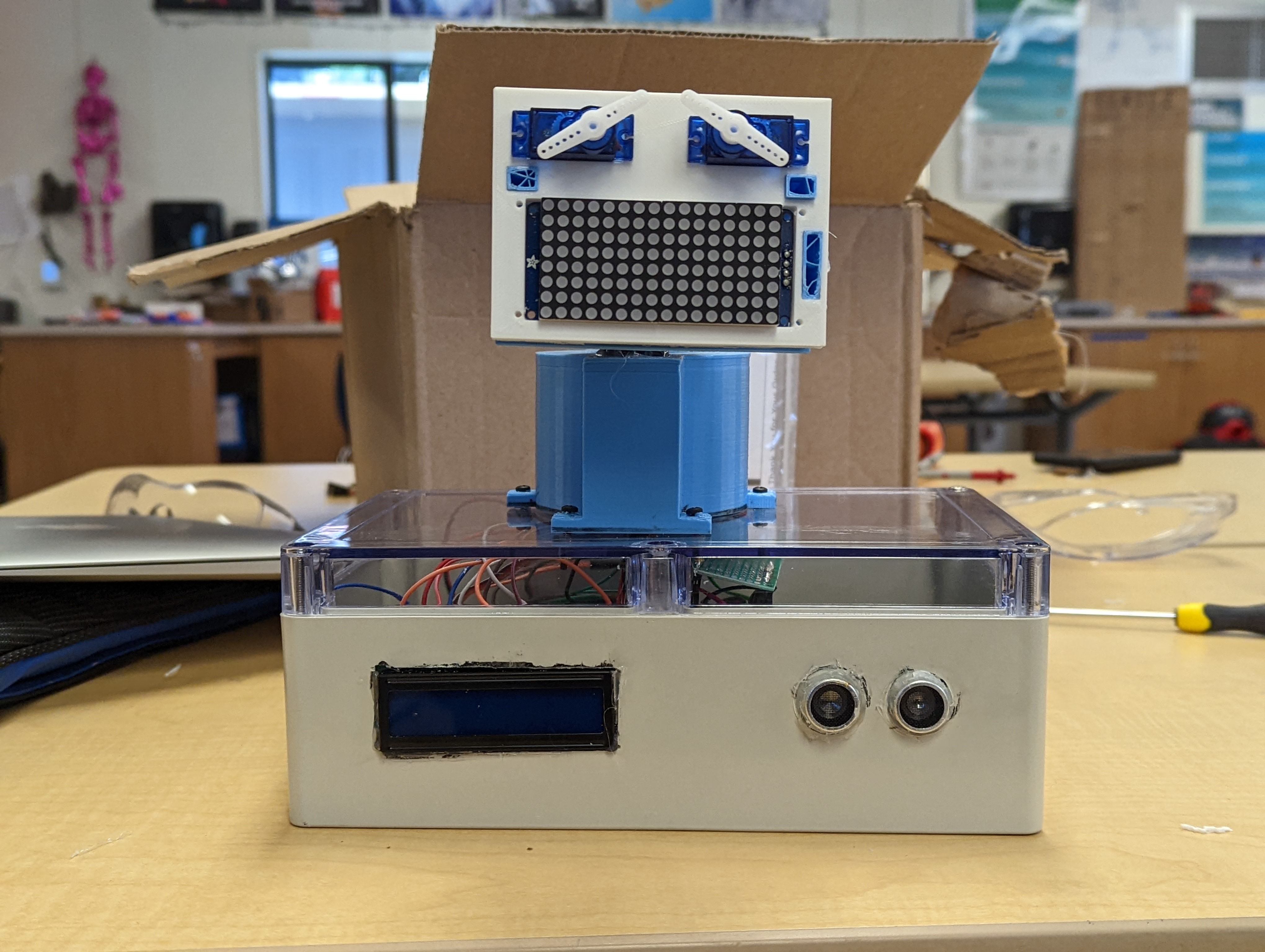
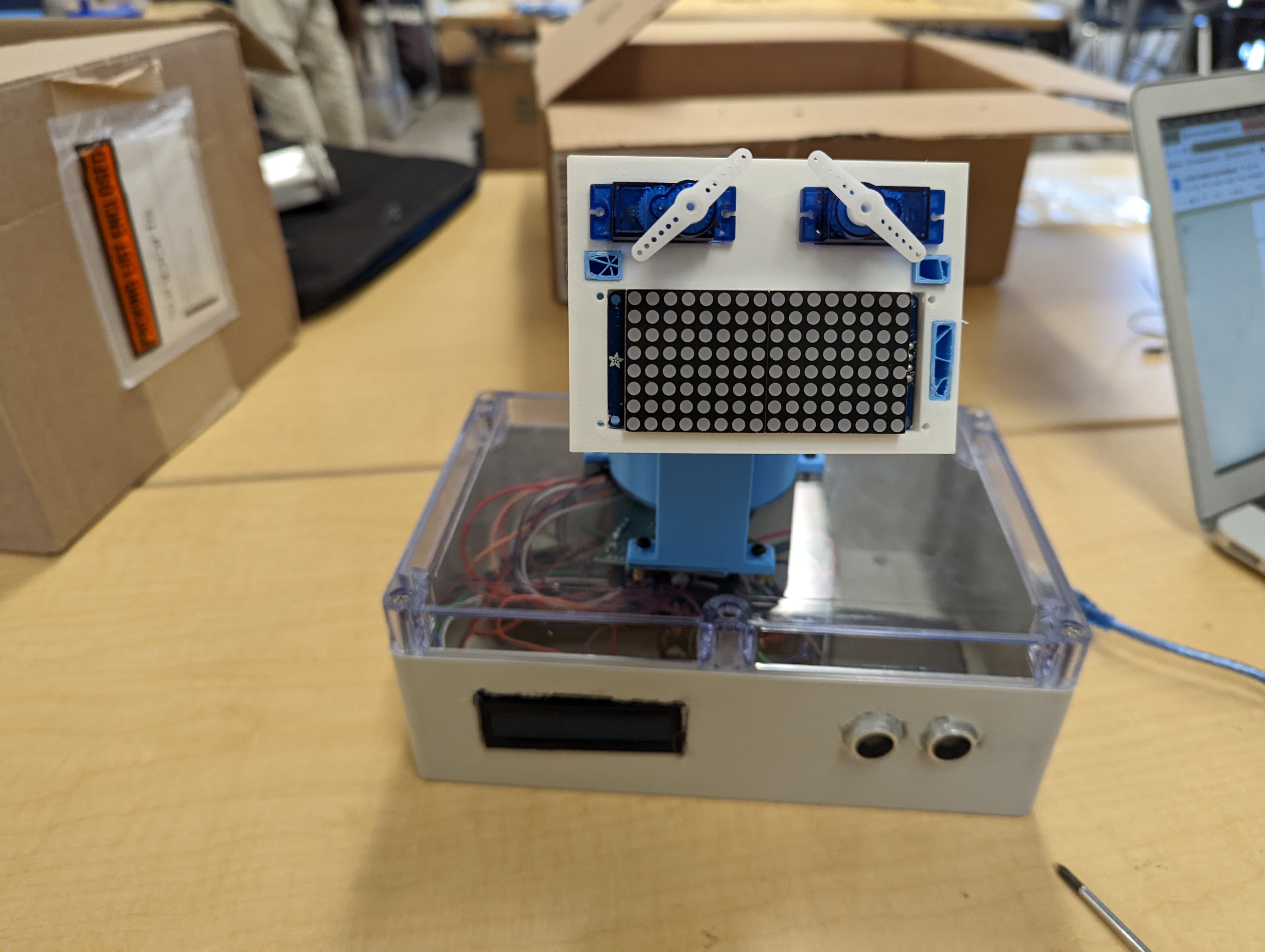
For my second milestone I finished the project. I used Computer-Aided-Design(CAD) to make 2 of the 3D-printed pieces and it was not the most enjoyabe experienence. Onshape(the CAD software I used) was a bit finniky for me and getting measurements right took a long time, compounded with the fact that many times the sketches I made couldn’t exist according to the software, I had to make the face plate and mount many times. The ultrasonic sensor is how the robot gets the input. The sensor sends out a sound and measures the time it takes for the sound to return to it in microseconds to calculate distance in cm. Depending on how far something is from the robot it will either be angry, happy, or scared. The byte arrays are different for each emotion and the pan and tilt servos can move if the robot is angry as well.
First Milestone
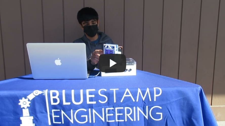
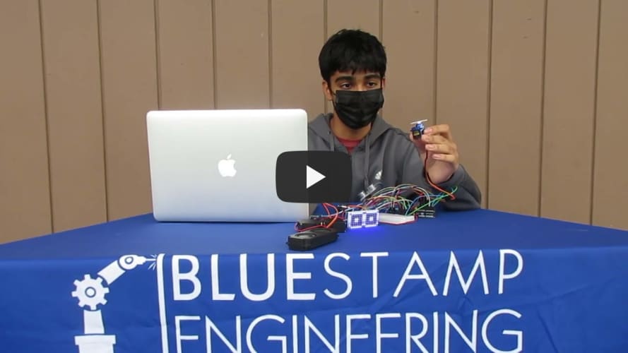
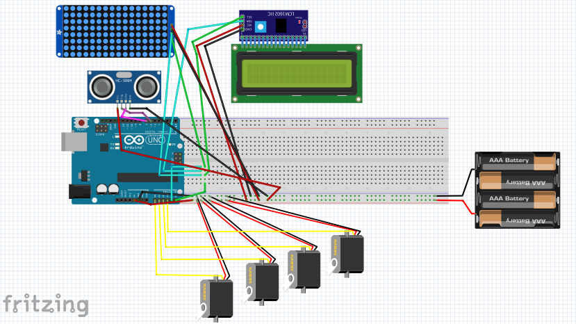
My first milestone was wiring everything up and getting different bits and pieces of the robot to work. I also made some of the pieces(ultrasonic sensor, 16x8 matrix, and 16x2 matrix) work at the same time. There were ups and downs during all this. For example in the 16x8 matrix the solder was connected to the copper underneath, causing it to short circuit. It was resolved quickly once it was noticed and nothing was damaged. Making the byte arrays for the 16x8 matrix was very relaxing for me. It was a simple task I could be creative with and it was a good change of pace compared to the other parts of the project.
Starter Project
My starter project was the useless machine. It had 2 switches, a LED light, and an arm attatched to a motor. The electric motor operates through the interactions between the motor’s magnetic field and electric current in a wire winding to generate force in the form of torque applied on the motor’s shaft, which is what moved the arm. I enjoyed soldering the parts together, but I had some difficulties with the switch as the solder got on the other side of the board, and I was not able to get it out, so I had to redo the project. I also had some issues with putting the box together because the columns were self-threading so there were issues with getting the screws in. In the end we used power tools to help get the screws in.